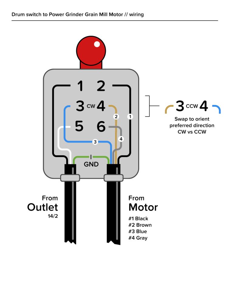
Typical Wiring Diagram For Drum Controller
Dashed lines indicate a single purchased component. Each component ought to be placed and connected with other parts in particular way.
[DIAGRAM] Forward Reverse Drum Switch Wiring Diagram FULL Version HD Quality Wiring Diagram

Electric latch retraction, with auto operator.

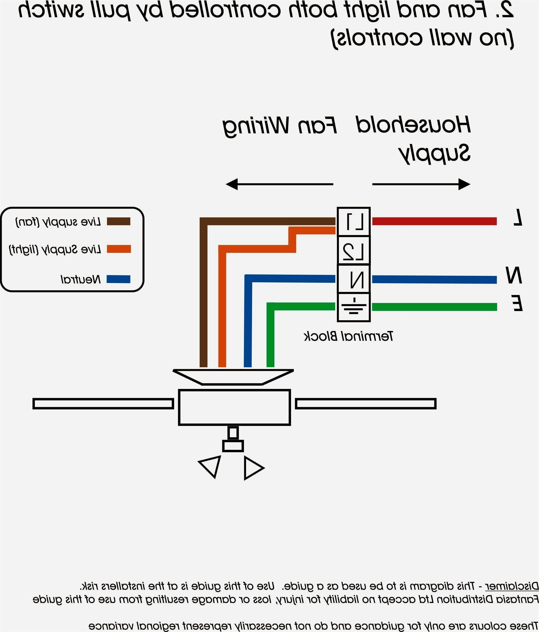
Typical wiring diagram for drum controller. This book contains examples of control circuits motor starting switches and wiring diagrams for ac manual starters drum switches starters contactors relays limit switches and lighting contactors. Typical house light wiring diagram. If you have a look at the front of a tv remote youll see the ir transmitter led.
Eo is the output voltage; To be able to install and calibrate basic instruments. Dayton drum switch wiring diagram.
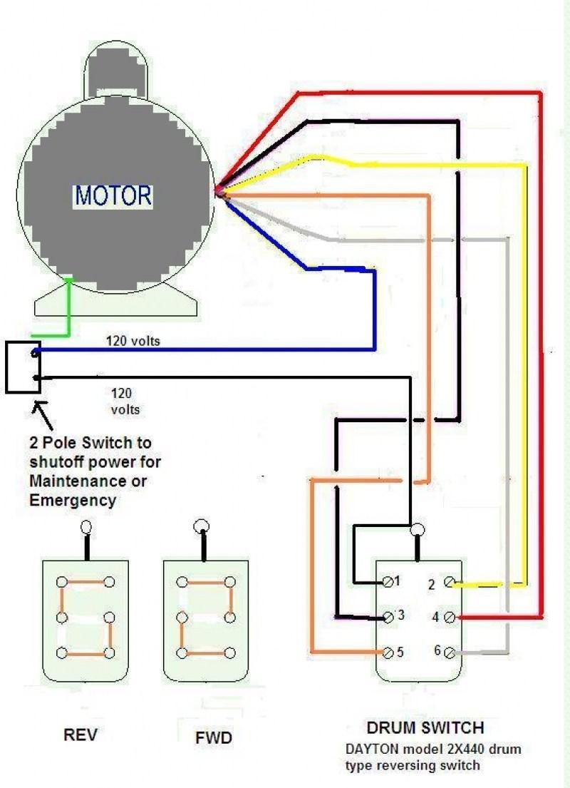
Before proceeding with the line voltage wiring instructions, the up and down limits of each motor should be set using the somfy tester cable (cat. This system uses 3 phase ac power (l1, l2 and l3) connected to the terminals. The dayton motor is a little more unusual.
Print the cabling diagram off plus use highlighters to trace the routine. Apply basic instrumentation to control an industrial process. Refer to the limit switch instructions packaged with each somfy motor for more information.
The three phases are then connected to a power interrupter. Consider a clothes dryer for example. Wiring diagram book a1 15 b1 b2 16 18 b3 a2 b1 b3 15 supply voltage 16 18 l m h 2 levels b2 l1 f u 1 460 v f u 2 l2 l3 gnd h1 h3 h2 h4 f u 3 x1a f u 4 f u 5 x2a r power on optional x1 x2115 v 230 v h1 h3 h2 h4 optional connection electrostatically shielded transformer f u 6 off on m l1 l2 1 2 stop ol m start 3 start start fiber optic transceiver class.
Do note that wiring the motor to a different voltage than what it is rated for may result in permanent damage. Use a 4mm x 2 core cable for your active and earth wires to the brakes separate from wiring used for lighting etc. Typical automatic transfer switch diagrams technical information.
Typical wiring diagram line diagrams show circuits of the operation of the controller. Dayton drum switch wiring diagram for electric motor. R1, r2, and r3 are fixed resistors;
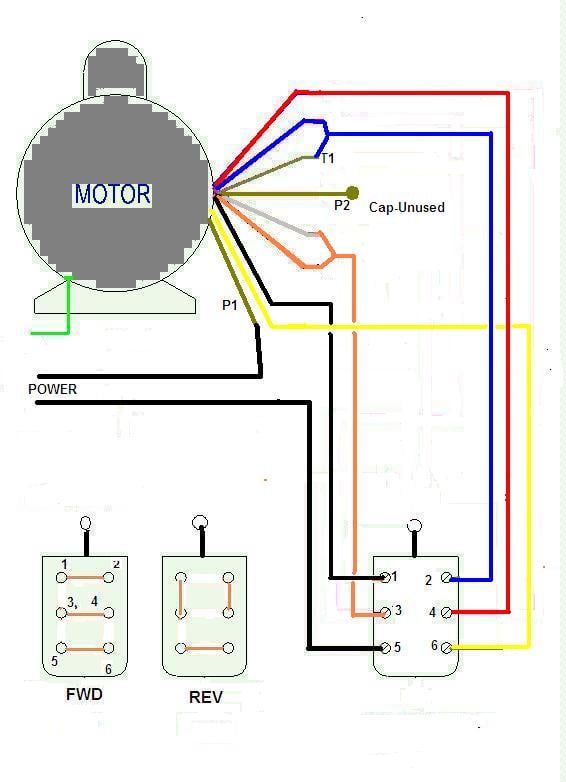
They can be used as a guide when wiring the controller. + other fans as shown brown black blue m 1~ green/y ellow brown cap black ce31 only single phase ac motor with capacitor blue or grey a n sildes these diagrams mainly apply to. I have included an image of the motor wiring diagram from the vfd manual below.
I bought the packard cb contactor 2 pole 30 amps coil voltage. A diagram that uses lines to represent. The simplest schemes are shown below.
Depending on the voltage you have measured in the first step, you should select the appropriate diagram. Rc control conircl mcdu1f con 1 rot. Dayton electric motor wiring diagram.
The following common wiring diagrams are available: In this uncompensated circuit, lead resistance l1 and l2 add directly to rt. One single door with panic bar.
This controller features a patented accelerometer design which senses the deceleration of the towing vehicle and sends a proportional voltage to the electric trailer brakes. Read p&ids (process and instrumentation diagrams). An example of a wiring diagram for a motor controller is shown in figure 1.
Apply simple design of control loops used in processes. Access control with electric strike and lcn 4600 automatic operator; Dexter electric brakes wiring diagram.
Typically, you will have two distinct diagrams. One will be for low voltage and another for high voltage connections. The block diagram below shows a typical vfd installation.
Note that symbols are discussed in detail later). Pilot light l2 4 2 3 pilot light start stop bulletin 1495 normally closed auxiliary contacts are required. Es is the supply voltage;
The four panels 4 led acid batteries 350w inverter wiring. Economical manual motor controller is enclosed in a weatherproof ip65 non metallic enclosure. They show the relative location of the components.
This form of electrical diagram is sometimes referred to as a “schematic” or “line” diagram. 2 technical information standard ats diagrams purpose of the document the purpose of this document is to propose a technical solution based on socomec motorised changeovers and. Understand feedback, feedfoward, cascade and ratio control.
Be used as a guide when wiring the controller. And rt is the rtd. Reverse switching of single phase motor forward 3 control using plc ladder sot reversing a motors with drum switch electrical controller wiring.
Typical Starter Wiring Diagram Nice Typical Wiring Diagram, Drum Controller Operation Of A.C

Need some help wiring a motor to a drum switch plz
[DIAGRAM] 3 Phase Drum Switch Wiring Diagrams Dayton
Grainger Drum Switch 115 Volts Wiring Diagram
Need help with hook up on a furnas j5 drum switch hooked to a marathon 1 1/2 ac cap/ start 6

220V Single Pole Switch Wiring Diagram Creative Wiring Single Phase Motor Drum Switch Random 2

19 Beautiful Square D Drum Switch Wiring Diagram
Reversing Drum Switch Wiring Diagram

Reversible Drum Switch Wiring Diagram For Motor Complete Wiring Schemas
Wiring A 110V Switch Diagram Popular 110V Drum Switch Wiring, Circuit Diagram Symbols

Reversing Drum Switch Wiring Diagram Diagram Light Switch Wiring Diagram Single Phase 230 Full

[DIAGRAM] Forward Reverse Drum Switch Wiring Diagram FULL Version HD Quality Wiring Diagram

Typical wire diagram of drum control AC wound rotor motor Schematic drawing, Diagram, Segmentation

Reversing Drum Switch Wiring Diagram

1E1F58 Bremas Drum Switch Wiring Diagram Ebook Databases
Dayton Reversing Drum Switch Wiring Diagram Wiring Diagram

Cutler Hammer Drum Switch Wiring Diagram Collection
Drum Switch Rewiring by wlw_19958 Homemade rewiring of a drum switch to enable a Dayton

A 3 Phase Drum Switch Wiring Diagrams Dayton Diagram Source
